Hardware
Serial connection box
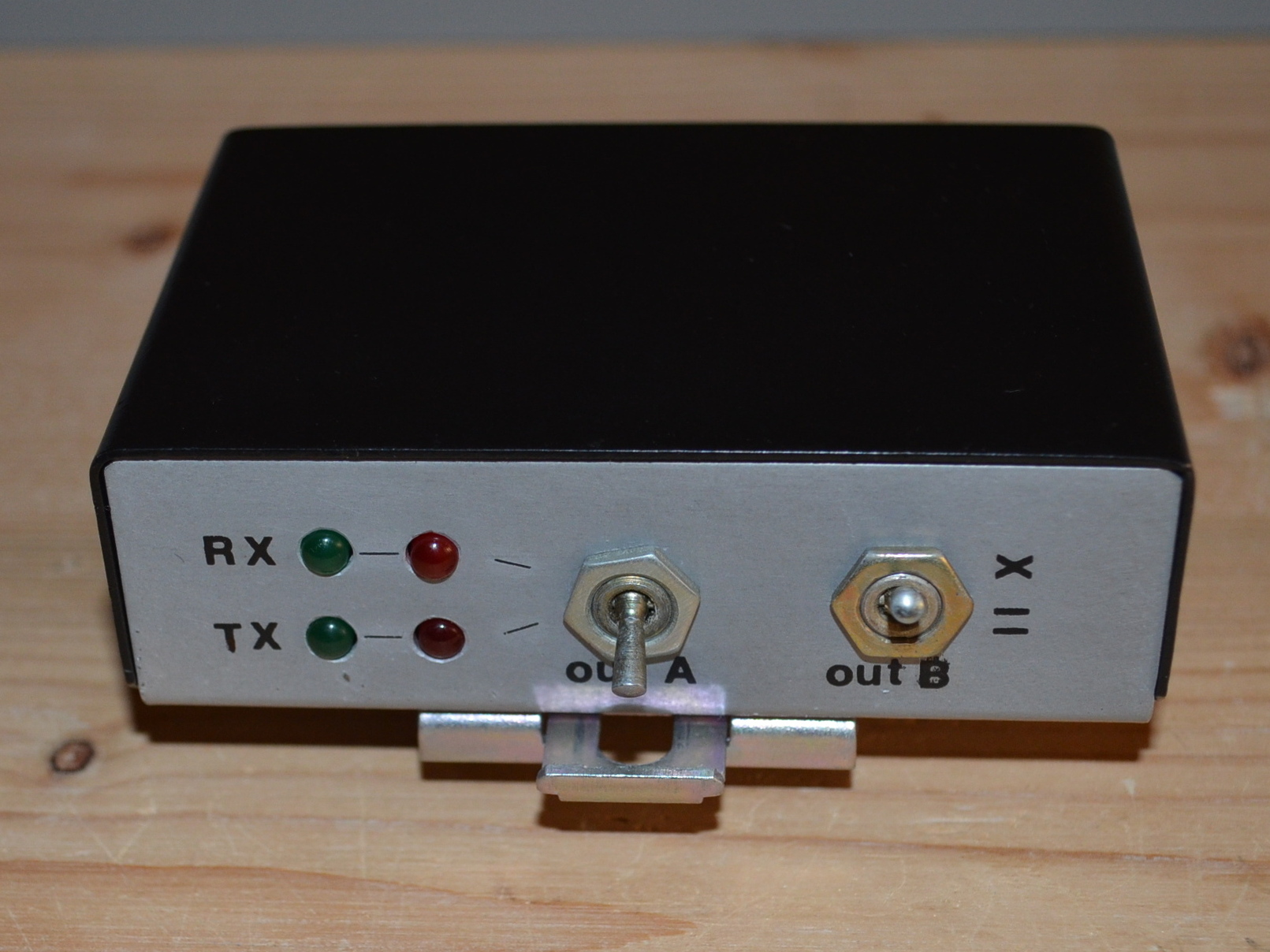
The device can be attached to a DIN rail with the help of the fastener mounted on the bottom.

Schematic
The schematic can be found in the attached materials. (OrCAD/SDT III v3.21 [1989] format and PostScript format.)Cables
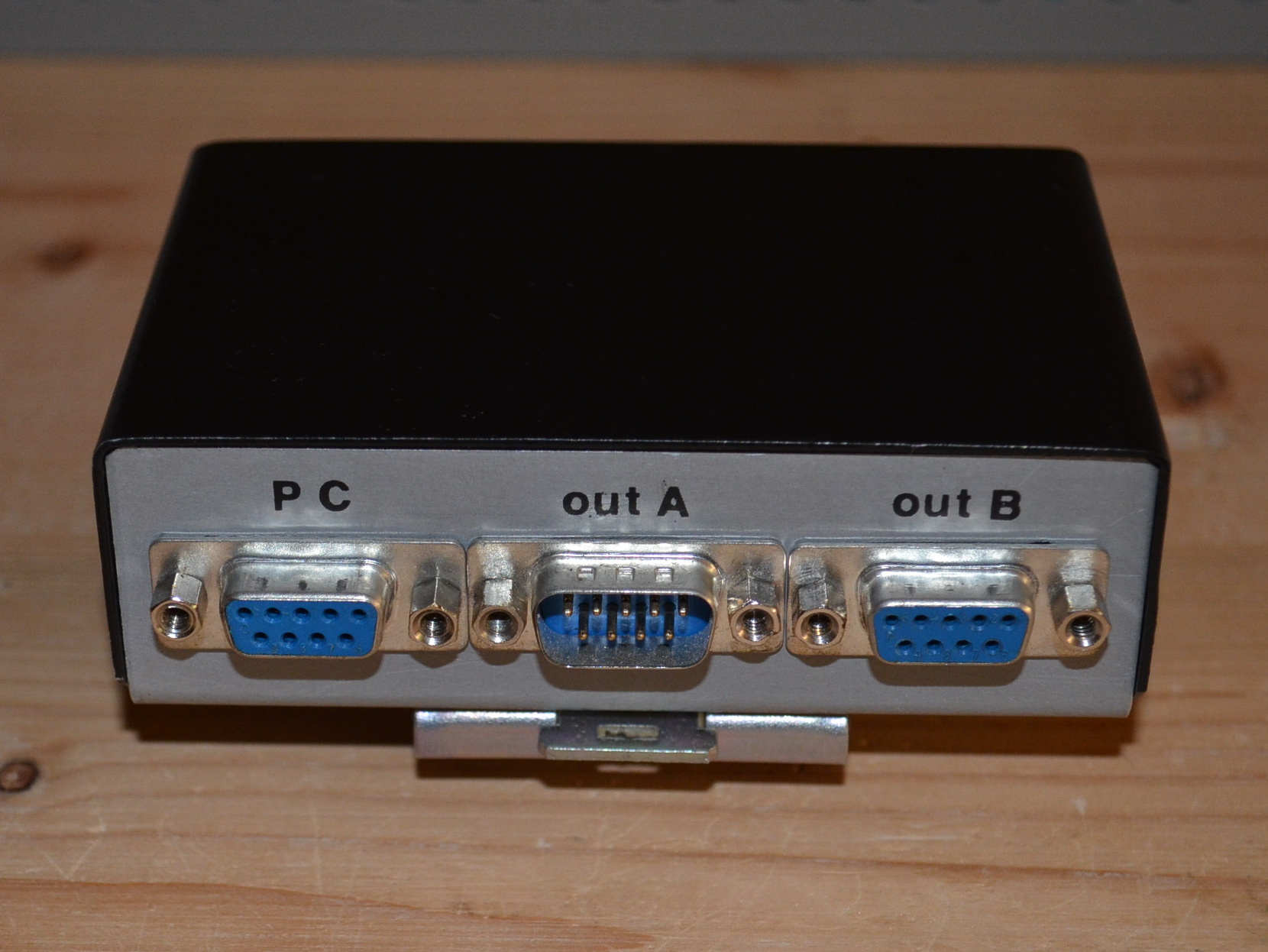
The cables connected to the PC and the Out B port are straight modem cables. The cable connected to the Out A port is a null-modem cable. Only RXD, TXD and GND are soldered in each cable.
How to use?
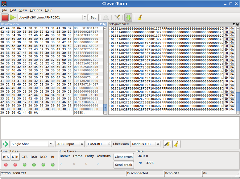
The control computer must be connected to the PC port, the monitoring computer must be connected to the Out A port, and the device must be connected to the Out B port. ModBUS/ASCII traffic can also be monitored with a simple serial terminal (e.g. Telix, Minicom), but it is more convenient to use a special program for this (e.g. CleverTerm).
Download
| name | version | type | note |
| Schematic drawing | zip | OrCAD/SDT III v3.21 (1989) |
 Project page on Hackster.io