Hardware
Mini serial console with three different serial ports
Hardware
It is a simple serial console that can be used for data display and data input. It can handle three (different) serial interfaces at the same time: 3.3V TTL for single-board computers and microcontrollers, via traditional RS-232 and serial over USB.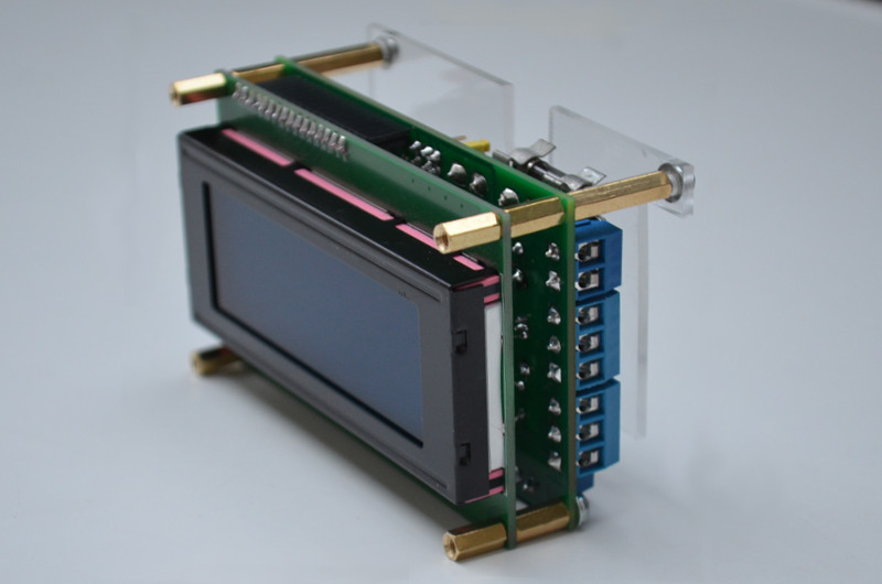
| supply voltage: | 5 V |
| current consumption: | approx. 30 mA |
| mechanical dimensions: | 100x60x50 mm |
| insulation class: | Class 0 |
| IP protection: | IP 00 |
| device housing material: | thermoplastic (PC), cover only |
| display size: | 20x4 characters |
| character set: | ASCII 32-127 |
| connection: | 3.3V TTL, RS-232 and USB serial |
| receive buffer size: | 255 byte |
The circuit has three serial ports, depending on the setting, all three can be used for data and system message transmission, or both at the same time. The #0 serial port is via USB port, #1 is a 3.3V TTL port, #2 is a conventional RS-232 serial port. Serial #1 can be connected to a 5V TTL serial port with an external level shifter circuit. Default port speeds: 115200, 9600 and 9600 bit/s, these values can be set in the program.
The console has four operation modes, the first three for display only can be used, these are pre-programmed, the fourth is reserved for unique solutions. With jumpers between modes we can choose.
Modes of operation:
| MODE #0 | read only mode, no cursor, 20x4 size displayed area 80x4 size on a virtual screen, automatically scrolls the lines, a displayed area can be moved horizontally a with push buttons. |
| MODE #1 | read only mode, no cursor, 20x4 display area On a virtual screen of size 80x25*, automatically scrolls the rows, the displayed area horizontally and can be moved vertically with the push buttons. |
| MODE #2 | read only mode, no cursor, 20x4 displayed area 80x25 On a virtual screen of size *, the displayed area can be moved horizontally and vertically with the push buttons, after FormFeed (0x12) a new, clean page starts. |
| MODE #3 | reserved for device dependent solutions (menu, read/write mode etc.). |
Function of buttons:
| button | MODE #0 | MODE #1 | MODE #2 | MODE #3 |
| PB0 | ← | ← | ← | ← |
| PB1 | → | → | → | → |
| PB2 | ↑ | ↑ | ↑ | |
| PB3 | ↓ | ↓ | ↓ | |
| PB4 | ENTER | |||
| PB5 | ESCAPE |
Software
The program that operates this device was created on the Arduino IDE development system. This application must first be prepared to work with the Raspberry Pi Pico, for which instructions can be found online (for example here).Setup
Before installing the program, you need to set these prepocessor macros:#define LCD_8BIT // enable 8 bit mode of the LCD #define COM_USB // enable Serial #0 port #define COM_TTL // enable Serial #1 port #define COM_RS232C // enable Serial #2 port // #define COM_USB_MESSAGES // enable console messages on Serial #0 port // #define COM_TTL_MESSAGES // enable console messages on Serial #1 port // #define COM_RS232C_MESSAGES // enable console messages on Serial #2 portand constants:
const int     lcd_bloffinterval = 60000;                // LCD backlight off time
const byte    lcd_xsize         = 20;                   // horizontal size of display
const byte    lcd_ysize         = 4;                    //vertical size of display
const byte    virtscreenxsize   = 80;                   // horizontal size of virtual screen
const byte    virtscreenysize   = 25;                   // vertical size of virtual screen
const int     com_speed[3]      = {115200, 9600, 9600}; // speed of the USB serial port
How it works?
At start-up, the program initializes serial ports and if consol messages is enabled sends status message. After that, it sets the GPIO ports, clears the virtual screen and initializes the display. Sets its own operating mode according to the jumpers (JP2-3). The display shows brief information about the device.The program then continuously monitors all serial ports, the state of the buttons, and the state of the mode selection jumpers. If data is received on one of the ports, it is copied to the virtual screen. The LCD display shows a part of the virtual screen as a window. This 'window' can be moved with the buttons. The size of the virtual screen and the ability to move the 'window' depend on the selected mode.
The program turns off the backlight after 60 s of inactivity, then turns it back on when data is received or a button is pressed.
The program replaces the incoming TAB character (0x09) with SPACE (0x20), blinks the backlight in response to the BEL (0x07) character, and starts a new page to the FF (0x0B) in mode #2.
Manuals and connectors
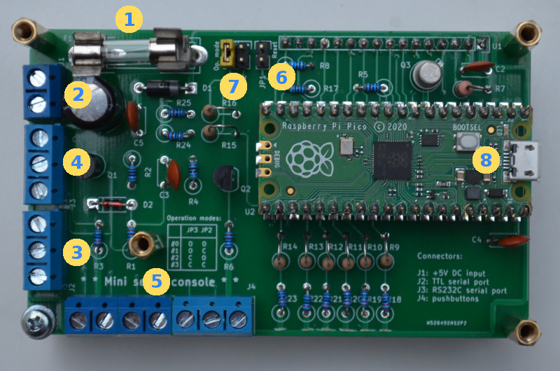
| 1: | Fuse F1 - power supply |
| 2: | J1 connector - power input |
| 3: | J2 connector - TTL serial port |
| 4: | J3 connector - RS-232 serial port |
| 5: | J4 connector - push buttons |
| 6: | JP1 jumper - RESET |
| 7: | JP2-3 jumpers - mode selector |
| 8: | USB connector |
Schematic

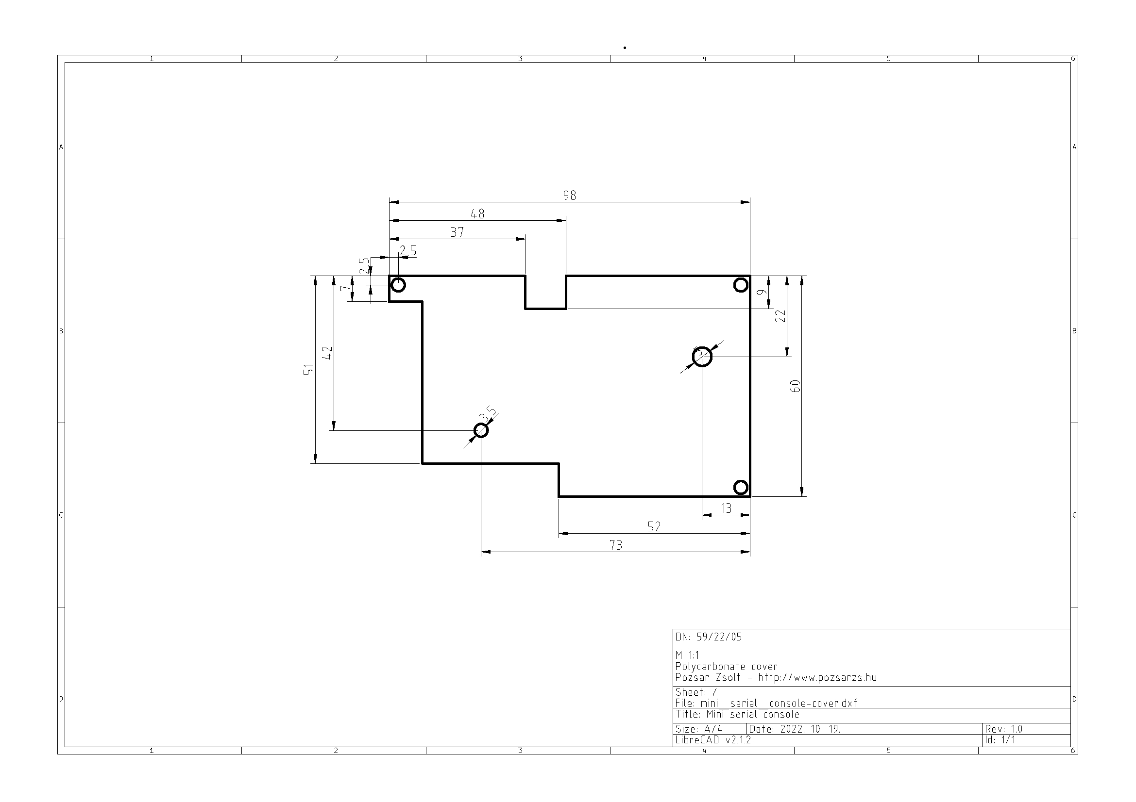
Polycarbonate cover
Download
| name | version | format | comment |
| hardware documentation | v220726 | tar.gz | |
| only Gerber files | v0.1 | zip | Order here:  |
Operation program
| name | version | OS | arch. | format | note |
| source package | v0.1 | tar.gz | C++ | ||
| binary package | v0.1 | arm | tar.gz |

git clone https://github.com/pozsarzs/mini_serial_console-hw.git git clone https://github.com/pozsarzs/mini_serial_console-sw.git Project page on Hackster.io